3GPP
http://www.3gpp.org/
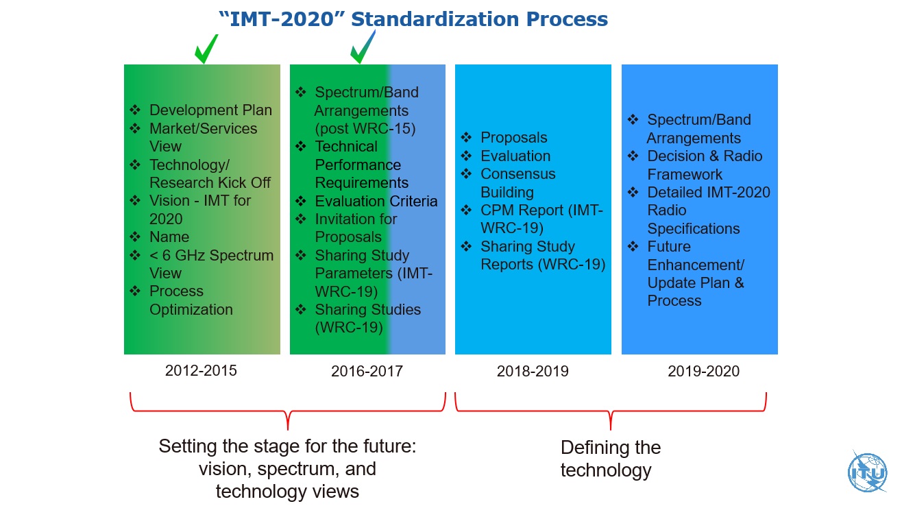
What is the 3GPP standard 5G why organizations cannot do without it?
Time flies, blink of an eye to 2017, from its inception in 1998, 3GPP continues to expand, driven by the members, involve a lot of work and hundreds of companies Collaboration, including network operators, terminal manufacturers, chip manufacturers, infrastructure manufacturers, academia, research institutions, government agencies, accumulated to more than 6,000 participants in 2017, good guys, great.
http://news.mydrivers.com/1/562/562043.htm
access network and core network
Evolution from 3G to 4G, the access network and the core network “integrated” to the 4G era.
to 5G is not the same, 3GPP organization to access network (5G NR) and core network (5G Core) apart, to independently evolve to 5G era.
4G wireless access is called eLTE, and 5G base station wireless access is called New Radio, abbreviated NR.
5G, in the first stage, eLTE will follow with NR and the common 4G core network. Then the network evolves slowly and NR will access its own core network, which may happen in the second phase of 5G.
5G 3 scenes
- eMBB (Enhanced Mobile Broadband): Enhanced mobile broadband (bands below 6 GHz)
- URLLC (Ultra-Reliable Low-Latency Communications): Ultra-reliable low-latency communication (bands below 6 GHz), such as unmanned services.
- mMTC (massive Machine Type Communications): Large-scale machine communication/large-scale Internet of Things (under 6 GHz band)
Note that these three terms will be widely used in future communications.
5G NR
3G base stations called the NodeB (NB)
4G base station called the eNB (Enhanced NB)
What is the 5G base station called?
3GPP give it a name, GNB
The wireless access of the 5G base station is called New Radio, abbreviated NR
5G NR’s “self-introduction” http://www.eefocus.com/communication/408007
LDPC/Polar
I don’t know if my friends can remember that in late November 2017, Huawei’s main (Polarization Code) scheme won 5G as the control scheme for the control channel. The eMBB scenario of one of the three scenarios developed by 3PGG , and the Qualcomm-led LDPC code is used as the coding scheme for the data channel.
According to Huawei’s actual test, the Polar code can meet the requirements of ultra-high-rate, low-latency, and large-connection scenarios, and can increase the spectrum of the cellular network by about 10%, and combine with millimeter waves to achieve 27Gbps. rate.
For the eMBB scenario, with Huawei’s main force, plus Qualcomm’s support, I believe that wireless communication technology can be upgraded to a new height.
4G mobile communication network architecture
the UE (User Equipment)
E-the UTRAN (Access Network)
the EPC (Core Network)
the MME: Mobility Management the Entity
S-GW: the Serving the GateWay, serving gateway
P-GW: the PDN the GateWay, the PDN gateway
E-the UTRAN: Evolved Universal Terrestrial Radio Access the Network
the EPC: Evlved packet core evolved packet core
the RRC: radio refers to the resource control RRC
the PDCP: packet the data convergence protocol packet data convergence protocol
the RLC: radio link control RLC layer protocol
PHY: Physical Layer Protocol

User and Control Surfaces
https://blog.csdn.net/wowricky/article/details/6907715
go user plane data
go control plane signaling
eNodeB function
includes physical layer functions (HARQ, etc.), MAC, RRC, scheduling, radio access control, mobility management.
gateway
Everyone knows that going from one room to another is bound to go through a door. Similarly, sending information from one network to another must also go through a “gateway”, which is the gateway. As the name suggests, a gateway is a “gateway” in which a network connects to another network.
Assuming your name is small (small), you live in a large yard, your neighbor has many small partners, and your parents are your gateway. When you want to play with a little friend in the yard, as long as you yell at his name in the yard, he will respond to you when he hears, and run out to play with you.
But your parents don’t allow you to get out of the door. Everything you want to do with the outside world must be contacted by your parents (gateway) to help you. If you want to chat with your classmate Xiao Ming, Xiao Ming’s family lives in another yard far away. He also has parents at home (Xiao Ming’s gateway). But you don’t know the phone number of Xiao Ming’s home, but your class teacher has a list of all the classmates in your class and a phone number comparison table. Your teacher is your DNS server. So you have the following conversation with your parents at home:
Small point: Mom (or Dad), I want to find the class teacher to check Xiaoming’s phone number line?
parents: Well, you wait. (Then your parents hang a phone call to your class teacher and ask Xiao Ming’s phone.) Asked, his home number is 211.99.99.99 Little is not too good: great! Mom (or dad), I want to find Xiao Ming, you can contact me for Xiao Ming.
parents: no problem. (Then the parent sent a request to the telephone office to call Xiaoming’s phone. The last level was of course transferred to the Xiaoming’s parents, and then his parents transferred the call to Xiaoming)
So you got in touch with Xiao Ming.
If you figure out what a gateway is, the default gateway is well understood. Just like a room can have multiple doors, a host can have multiple gateways. The default gateway means that if a host cannot find an available gateway, it will send the packet to the default gateway, which will process the packet. Default gateway. The default gateway is usually filled in 192.168.x.1
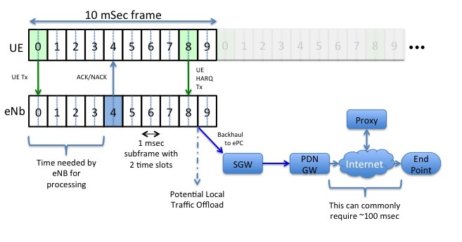
retransmission mechanism
ARQ and HARQ
HARQ: Hybrid Automatic Repeat reQuest (HARQ) https://www.jianshu.com/p/f8650640660b
BBU and RRU
RRU is the Remote Radio Unit remote radio module, and the BBU is the Building Baseband Unit indoor baseband processing unit.
The baseband BBU is placed in the equipment room in a centralized manner. The RRU can be installed to the floor. The BBU and the RRU are connected by optical fiber. The RRU is connected to the antenna through a coaxial cable and a power splitter (coupler), that is, the trunk uses optical fiber. The road uses coaxial cable.
For the downlink direction: the optical fiber is directly connected to the RRU from the BBU, and the baseband digital signal is transmitted between the BBU and the RRU, so that the base station can control a certain user’s signal to be transmitted from the designated RRU channel, which can greatly reduce the local cell. User interference on other channels.
For the uplink: the user’s phone signal is received from the nearest channel, and then transmitted to the base station through an optical fiber from the channel, this also can greatly reduce the interference between users on different channels.
Active and passive antennas
Passive Antenna: It is purely a metal body and is a variety of antennas that are commonly seen.
active antenna: this is the normal antenna and amplifier is to improve sensitivity and to reduce signal noise.
GPS antenna using the difference between active and passive
http://www.arsgps.com/ Changjianwenti/30-80.html
QoS
IP address
The so-called IP address is a 32bit address assigned to each host connected to the Internet . According to the TCP/IP protocol, the IP address is expressed in binary. Each IP address is 32 bits long, and the bit is converted into bytes, which is 4 bytes. For example, an IP address in binary form is “00001010000000000000000000000001”. With such a long address, people are too hard to handle. In order to facilitate people’s use, IP addresses are often written as ” strong” in decimal form, and different characters are separated by the symbol “.” in the middle. Thus, the above IP address can be expressed as “10.0.0.1”. This representation of the IP address is called “ dotted decimal notation“, which is obviously much easier to remember than 1 and 0.
Each IP address contains two parts: Network ID and Host ID. Every computer on the entire Internet is identified by its own unique IP address. IP addresses form the basis of the entire Internet, and it is so important that each networked computer does not have the right to set its own IP address. There is a unified agency (IANA) that assigns a unique network ID to the organization of the application. The application organization can assign a unique host ID to each host in its network, just as a unit does not have the right to determine the street name and house number of the city in which it belongs, but can independently determine the individual office numbers within the unit.
According to the different number of digits of the network ID and host ID, the IP address can be divided into A (7-bit network ID and 24-bit host ID), B (14-bit network ID and 16-bit host ID), C (21) There are three types of bit network IDs and 8-bit host IDs. Due to historical reasons and differences in technology development, Class A addresses and Class B addresses are almost completely depleted. Currently, only Class C addresses can be allocated to organizations in various countries around the world. So IP address is a very important network resource.
The IP address and subnet mask are combined to obtain the network ID and host ID.
For an organization that has set up an Internet service, because its host has opened access services such as WWW, FTP, E-mail, etc., it usually publishes a fixed IP address to facilitate user access. Of course, digital IP is inconvenient to remember and recognize. People are more accustomed to accessing a host through a domain name, and the domain name actually needs to be translated into an IP address by a domain name server (DNS). For example, your home page address is www.myhost.com , which users can easily remember and use, and the domain name server translates the domain name into 101.12.123.234, this is your real address on the Internet.
For most dial-up users, it is highly undesirable to assign a fixed IP address (static IP) to each user due to the discrete time and space of the Internet. This will result in a huge IP address resource. waste. Therefore, these users usually get a dynamic IP address every time they dial the ISP’s host . This address is of course not arbitrary, but the network ID and host ID of the ISP are legal. An address in the interval. The IP address of the dial-up user when connecting twice is likely to be different, but the IP address does not change during each connection time.
5G NR spectrum
http://www.eefocus.com/communication/408007/p3
In the R15 version, two major FRs (frequency ranges) are defined:
LTE band number starts with B, such as LTE B20 (Band 20) The 5G NR band number identifier starts with n, and the 20th band in the 5G NR is called n20.
http://www.sharetechnote.com/html/5G/5G_FR_Bandwidth.html#Operating_Band
FDD/TDD/SDL/SUL
https://zhidao.baidu.com/question/91344791.html
- TDD means time division duplex. ( refers to the duplex mode) TDDUses time to separate the receive and transmit channels. In the TDD mobile communication system, different time slots using the same frequency carrier are received and transmitted as bearers of the channel, and time resources are allocated in two directions. The base station sends a signal to the mobile station during a certain period of time, and the time interval in the middle is sent by the mobile station to the base station, and the base station and the mobile station must cooperate in order to work smoothly.
- FDD means frequency division duplex. ( refers to the duplex mode, and the transceiver uses different frequencies.) FDD is used to receive and transmit on two separate symmetric frequency channels, and the guard band is used to separate the receiving and transmitting channels. The disadvantage of FDD is that it must use pairs of frequencies, relying on frequency to distinguish between uplink and downlink, and its unidirectional resources are continuous in time.
- SDL can only be used for downstream transmissions
- SUL can only be used for upstream transmissions
- Frequency Division Duplex Bands (FDD)
- Time Division Duplex Bands (TDD)
- Supplementary Bands: Supplementary Downlink Bands (SDL)
- Supplementary Bands: Supplementary Uplink Bands (SUL)
PAPR
https://baike.baidu.com/item/PAPR/5310514?fr=aladdin
Peak to Average Power Ratio (PAPR), referred to as peak-to-average ratio (PAPR).
The
MIMO-OFDM system provides greater coverage, better transmission quality, higher data rates, and spectral efficiency.
However, since the OFDM symbol is superposed by a plurality of independently modulated subcarrier signals, when the respective subcarriers have the same phase or similar , the superimposed signal is subjected to the same initial phase signal. The modulation, which produces a large instantaneous power peak, further leads to a higher peak-to-average power ratio (PAPR), referred to as peak-to-average ratio (PAPR).
Because the dynamic range of the general power amplifier is limited , the MIMO-OFDM signal with a relatively large peak is easy to enter the nonlinear region of the power amplifier, This causes the signal to produce nonlinear distortion, resulting in significant spectral spread interference and in-band signal distortion, resulting in severe degradation of overall system performance. The peak-to-average ratio has become a major technical obstacle to MIMO-OFDM.
Carrier Aggregation
Carrier Aggregation (CA) is to synthesize a fragmented LTE band into a wider frequency band of “virtual” to meet the certain preconditions to increase the data rate.
Carrier aggregation can use continuous bandwidth and discontinuous bandwidth, and bandwidth flexibility is great. A single carrier in carrier aggregation is called a CC (component carrier), and each CC can use any bandwidth (1.4, 3, 5, 10, 15, and 20 MHz) specified by LTE R8.


Physical layer of 5G-NR
http://www.eefocus.com/communication/408007/p4
OFDM symbol duration and number of subcarriers
- The duration of the OFDM symbol depends on the spacing of the subcarriers and the length of the CP.
- When the subcarrier spacing is constant, the number of subcarriers depends on the channel bandwidth. The number of subcarriers does not affect the duration of the OFDM symbol.
- When the channel bandwidth is constant, the subcarrier spacing is small, and more subcarriers can be placed, but the OFDM Symbol Duration becomes longer and the data transmission rate does not change. (The modulation is the same regardless of CP and other overhead, and the subcarriers fill the channel bandwidth).
For example, Let OFDM Symbol Duration be 1ms, the subcarrier spacing is 1kHz, when the channel bandwidth is 10kHz, 10 subcarriers can be placed. If the modulation is BPSK, the data transmission rate is 10×1bit/1ms=10kbps. If the subcarrier spacing becomes 0.5 kHz, 20 subcarriers can be placed, and the data transmission rate at this time is 20 × 1 bit / 2 ms = 10 kbps.
Visible, the highest transmission rate of an OFDM waveform is:
Currently 3GPP Release 15 has determined that CP-OFDM supports 5G NR uplink and downlink, and also introduces DFT-S-OFDM waveforms complementary to CP-OFDM waveforms. CP-OFDM waveforms can be used for single-stream and multi-stream (ie, MIMO) transmissions, while DFT-S-OFDM waveforms are limited to single-stream transmissions with limited link budget constraints.
Waveform (for eMBB/URLLC and <52.6 GHz) • DL Waveform: CP-OFDM • UL Waveform: CP-OFDM + DFT-s-OFDM
CP-OFDM targeted at high throughput scenarios DFT-s-OFDM targeted at power limited scenarios
Understanding the 5G NR Physical Layer
Multiple Access Multiple Access Scheme
- Orthogonal Multiple Access
- Non-Orthogonal Multiple Access (NOMA) not supported in Rel-15
physical channel bandwidth
http://www.eefocus.com/communication/408007/p5
In the frequency band less than 6 GHz (FR1), the maximum channel bandwidth of 5G NR is 100 MHz
in the millimeter wave band (FR2), and the maximum channel bandwidth of 5G NR is 400 MHz, which is much larger than the maximum channel bandwidth of LTE of 20 MHz.
But it is worth mentioning that the bandwidth utilization of 5G NR has increased significantly to over 97% (LTE bandwidth utilization is only 90%).
How to understand 5G NR enhance bandwidth utilization?
The
10 MHz 4G channel has 50 RBs, each RB has 12 subcarriers, and the 10 MHz 4G channel has a total of 600 subcarriers. Since each subcarrier has an interval of 15 kHz, 15*600 is equal to 9000 kHz or 9 MHz, which means that only 9 MHz is utilized in the 10 Mhz channel, and about 1 MHz is left as the guard band, so the bandwidth utilization of LTE is only 90. %. By analogy, a 20MHz 4G channel has 100 RBs, which uses only 18MHz in a 20MHz bandwidth; a 50MHz 4G channel has 250 RBs…
Guess what is the number of RBs in a 50MHz 5G channel? 275. (270×12×15e3)/50e6 = 99%
Numerology
Numerology This concept can be translated into a parameter set, which roughly means a set of parameters, including subcarrier spacing, symbol length, CP length, and so on. http://www.eefocus.com/communication/408007/p4
Scalable subcarrier spacing
The subcarrier spacing is a trade-off between the symbol duration and the CP overhead: the smaller the subcarrier spacing, the longer the symbol time length; the larger the subcarrier spacing, the larger the CP overhead.
5G NR The most basic subcarrier spacing is the same as LTE, it is also 15kHz, but it can be flexibly extended

 Understanding the 5G NR Physical Layer
TTI (Time Transmission Interval)
Qualcomm reference page
https://www.qualcomm.com / Invention / Technologies / NR-5g / Unified-AIR-interface
HTTPS: // WWW .eetimes.com/document.asp?doc_id=1278199
frame structure
http://www.sharetechnote.com/html/5G/5G_FrameStructure.html http://www.eefocus.com/communication/408007/p5
The length of the 5G radio frame and the subframe are fixed. The length of one radio frame is fixed to 10ms, and the length of one subframe is fixed to 1ms. This is the same as LTE, so as to better maintain the coexistence between LTE and NR, which facilitates synchronization of time slot and frame structure in the joint deployment mode of LTE and NR, and simplifies cell search and frequency measurement.
The difference between
is that the 5G NR defines a flexible sub-architecture, and the slot and character length can be flexibly defined according to the subcarrier spacing.
Therefore, we simply divide the 5G frame structure into two parts: a fixed structure and a flexible structure (see figure).
This is like building a house. The frame structure is fixed, and the space inside can be flexibly arranged according to your needs.
 Understanding the 5G NR Physical Layer
Resource Block
Resource Block (RB) Physical Resource Blocks (PRB) http://niviuk.free.fr/store_fiveg.php
Basic Concepts of LTE Resource Blocks
- RE (Resource Element): The minimum granularity of physical layer resources. Time domain: 1 OFDM symbol, frequency domain: 1 subcarrier
- RB (Resource Block) The resource allocation frequency domain minimum unit of the physical layer data transmission . Time domain: 1 slot, frequency domain: 12 consecutive subcarriers (Subcarrier)
- TTI: time-domain basic unit of physical layer data transmission scheduling 1 TTI = 1 subframe = 2 slots 1 TTI = 14 OFDM symbols (Normal CP) 1 TTI = 12 OFDM symbols (Extended CP)


Resource Grid
Understanding the 5G NR Physical Layer
- Resource elements are grouped into Physical Resource Blocks (PRB) – Each PRB consists of 12 subcarriers
http://www.sharetechnote.com/html/5G/5G_FrameStructure.html#Resource_Grid

☆
http://niviuk.free.fr/lte_resource_grid.html ☆
Slot
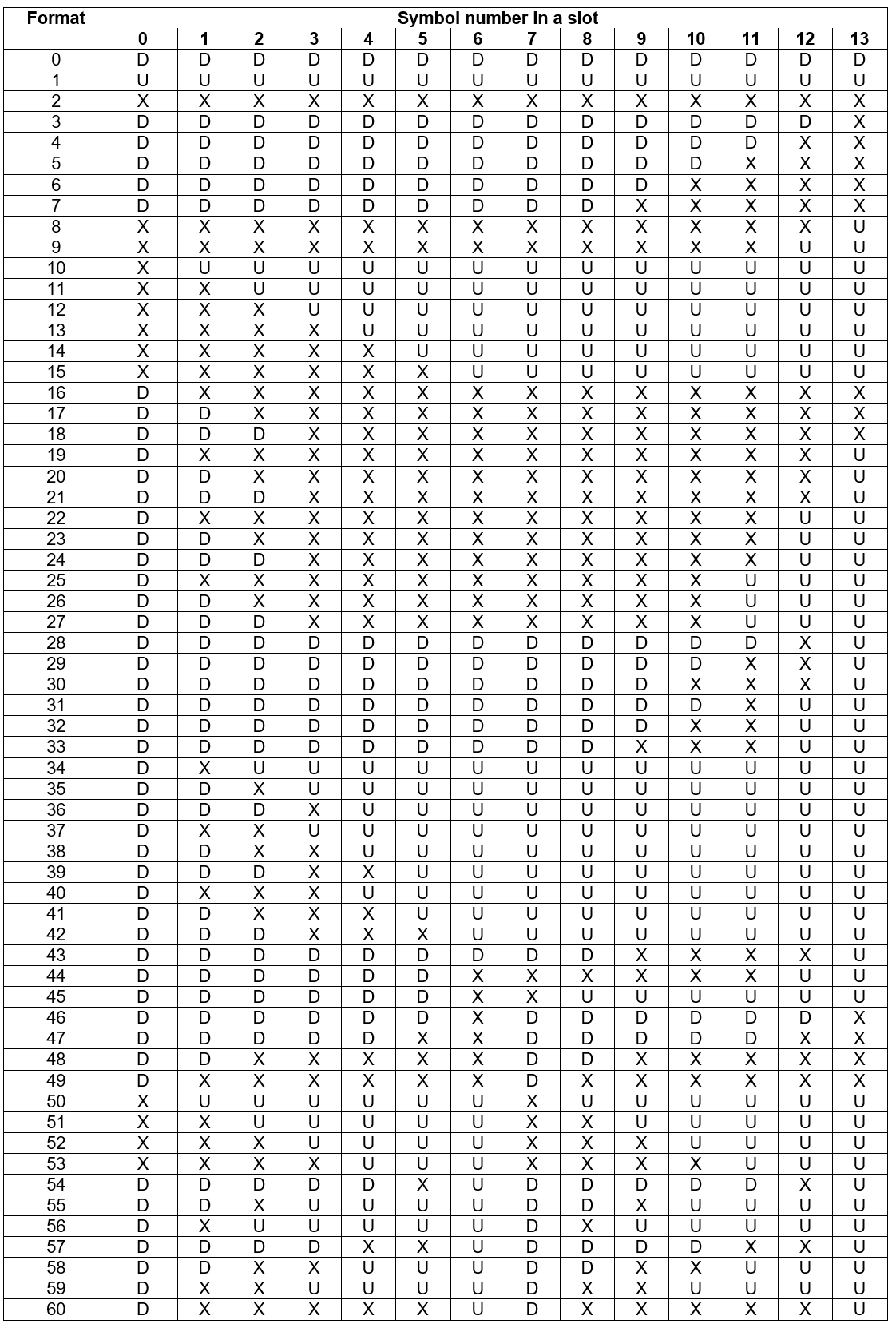
Slot Structure
Understanding the 5G NR Physical Layer
http://www.sharetechnote.com/html/5G/5G_FrameStructure.html#Slot_Format (Note # and the following section, you can link to a section of the page)
http://www.sharetechnote.com/html/5G/5G_FrameStructure.html#Resource_Grid
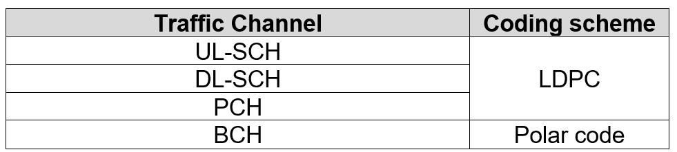
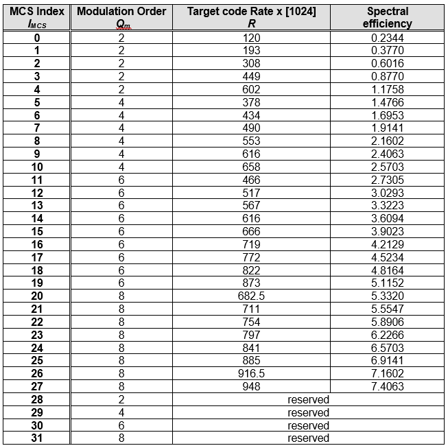
channel coding
5G NR data channel adopts LDPC code instead of LTE Turbo code; 5G NR broadcast channel and control channel adopt Polar code instead of LTE TBCC code.
Why does the data channel replace the Turbo code with an LDPC code?
Turbo code is characterized by low coding complexity, but high decoding complexity , and LDPC code is just the opposite . Considering that in the eMBB scenario, the code block is greater than 10000 and the code rate is up to 8/9, which is a serious injury to the Turbo code with high decoding complexity, and the decoding algorithm of LDPC is relatively simple and practical, just right.
It’s like having a song, just meeting you.
In addition, the use of LDPC essentially parallel processing mode, and the Turbo code is essentially serial and therefore LDPC scheme is applicable to low-delay applications .
As for the Polar code, although it is late, it has the characteristics of low coding and decoding complexity, and is very flexible. It has good performance at any code length and bit rate, and certainly becomes the control channel. Second choice.
Initial access and beam management
Understanding the 5G NR Physical Layer


Physical Channels and Signals
 SS Block SS Burst SS Burst Set


5G/NR – Synchronization
http://www.sharetechnote.com/html/5G/5G_Phy_Synchronization.html
NR Synchronization Process
When we say ‘ Synchronization ‘ in communication technology, it usually mean ‘ synchronization for transmission ‘ and 39; synchronization for reception ‘ .
In UE ‘ s point of view, ‘ transmitting direction ‘ is called ‘ Uplink ‘ and ‘ receiving direction ‘ is called 39; Downlink & # 39; . the Applying the this Terms to Synchronization Process, WE have have TWO types of Synchronization in Cellular Communication Including. 5G / NR Called & # 39; Downlink Synchronization & # 39; and & # 39 ; Uplink Synchronization‘ .
Donwlink Synchronization: This is the process in which UE detect the radio boundary (ie, the exact timing when a radio frame starts) and OFDM symbo boundary (ie, the exact timing when an OFDM symbol starts). This process is done By detecting and analyzing SS Block. This is a pretty complicated process and follow through SS Block Page for the detailed Understanding.
Uplink Synchronization: This is the process in which UE figure out the exact timing when it should send uplink data (ie, PUSCH / PUCCH). Usually a network (gNB) is handling multiple UEs and the network has to ensure that the Uplink signal from every UE should be aligned with a common receiver timer of the network. So this involves much more complicated process and sometimes it has to adjust UE Tx timing (uplink timing) of each UE. This is called RACH process. Of course, you need to go through much longer pages of reading. Read through RACH pagefor the details.
Overal Procedure of Synchronization and Initial Access
Overal Procedure of Synchronization and Initial Access
when we just say ” Synchronization ” , usually mean Downlink Synchronization. Of course, Uplink Synchronization is very important as well, but usually the uplink process is pursue as part of RACH process and normaly treated under ” RACH Procedure ” or ” Initial Access ” process .
How Synchronization work ?
The most common way to implement the Synchronization is
i) Create a predetermined signal (a predefined data sequence : This signal is called Sync signal)
ii) Put the signal into a specific OFDMA symbol in a specific subframe and transmit
Since UE already have (or can derive) all the details of the predetermined sync signal, it can search and detect the data from the stream of data reaching the UE. Because the sync signal is located in the predefined location in time, UE can detect the exact timing from the decoded sync signal.
What kind of Information can be derived from the Synchronizaiton Signal ?
Synchronization Signal in Frame Structure
Synchronization Signal in Frame Structure
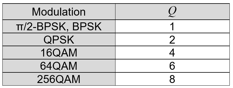
the order of modulation
Modulation Order
Wikipedia The modulation order of a digital communication scheme is determined by the number of the different symbols that can be transmitted using it.
- BPSK: The simplest forms of digital modulation are of second order because they can transmit only two symbols (usually stated as as ” 0 ” and ” 1 ” ).
- QPSK: 4th order modulation
- 16QAM: 16th order modulation
modulation order can be used to calculate the number of bits each modulation symbol can represent, log2 (modulation order) = n bit / symbol
LTE random access
Random access is essentially implementing uplink synchronization between the terminal and the base station, which is the air interface level. The essence of the attachment is to allow the terminal to successfully access the core network and successfully obtain the IP address, which is at the core network level.
http://www.sharetechnote.com/html/RACH_LTE.html
- RACH stands for Random Access Channel.
- This is the first message from UE to eNB when you power it on.
- In terms of eNB point of view, it would seem that it is getting this initial UE signal in almost random fashion (eg, in Random timing , Random Frequency and in Random Identification) because it has no idea when a user turn on The UE (Actually it is not completely random, there are a certain range of agreement between UE and Network about the timing, frequency location and possible indentification, but in large scale it would look like working in random fashion).
Why RACH ? (Why RACH is required)
The main purpose of RACH can be described as follows. i) Achieve UP link synchronization between UE and eNB Ii) Obtain the resource for Message 3 (eg, RRC Connection Request)
In most of the communication (especially digital comunication regardless of whether it is wired or wireless), the most important precondition is to establish the timing synchronization between the reciever and transmitter. So whatever communication technology you Would study, you would see some kind of synchronization mechanism that is specially designed for the specific communication.
synchronization in downlink: In LTE, the synchronization in downlink (Transmitter = eNB, Reciever = UE), this synchronization is achieved by the special synchronization channel (special physical signal pattern). Refer to Time Sync Process page for the details. This downlink sync signal gets broadcasted to everybody and it Is get transmitted all the time with a certain interval.
synchronization in uplink: However in Uplink(Transmitter = UE, Reciever = eNB), it is not efficient (actually waste of energy and causing a lot of interference to other UEs) if UE is using This kind of broadcasting/always-on synchronization mechanism. In case of uplink, this synchronization process should meet the following criteria i) The synchronization process should happen only when there is immediate Ii) The synchronization should be dedicated to only a specific UE All the complicated/confusing stories in this page is mostly about the process specially designed mechanism to meet these criteria.
Another purpose of RACH process is to obtain the resource for Msg3 (Message 3). RRC Connection Request is one example of Msg3 and there are several different types of Msg3 depending on situation.
Two types of RACH process
(http://www.sharetechnote.com/html/RACH_LTE.html#Two_types_of_RACH_process)
Two types of the RACH Process: Contention-based and Contention-Free
RACH Process Overview In Diagrams
http://www.sharetechnote.com/html/RACH_LTE.html#RACH_Process_Overview_In_Diagrams
CRC
CRC is the Cyclic Redundancy Check (Cyclic Redundancy Check): It is the most commonly used error checking code in the field of data communication, and its feature is that the length of the information field and the check field can be arbitrarily selected. Cyclic Redundancy Check (CRC) is a data transmission error detection function that performs polynomial calculation on data and attaches the result to the back of the frame. The receiving device also performs a similar algorithm to ensure the correctness and completeness of the data transmission. Sex.
https://blog.csdn.net/weicao1990/article/details/51669853
http://www.sharetechnote.com/html/Handbook_Communication_CRC.html
terminology
physical channel and physical signal
physical channels: A collection of a series of resource elements (RE: Resource Elements) for carrying information from higher layers.
physical signals (Signals PHYSICAL) : RE corresponding to a series of physical layer, but do not pass any information RE from the top. Such as reference signal (RS), synchronization signal. RS (Reference Signal): reference signal, also commonly referred to as pilot signal; SCH (PSCH, SSCH): synchronization signal, divided into primary synchronization signal and secondary synchronization signal.
logical channel and transport channel
logical channel (the Logical Channel)
transport channels (Transport Channe)
HTTP: //www.techplayon. Com/2411-2/
https://www.tutorialspoint.com/lte/lte_communication_channels.htm
http://www.rfwireless-world.com/Tutorials/LTE-logical-transport-physical-channels.html


LTE sync signal

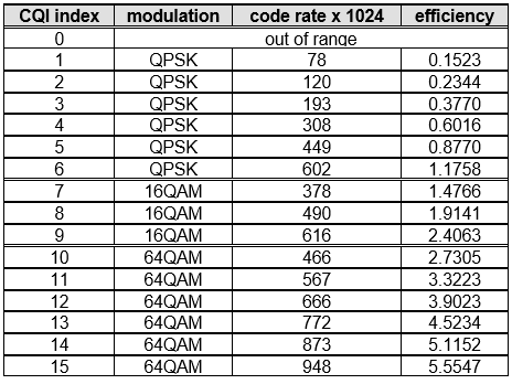
CSI
CSI (Channel State Information ) : Channel state information
https://blog.csdn.net/m_052148/article/details/72824979
In LTE, we usually refer to Channel State Information (CSI), which mainly includes PMI, RI, and CQI. PMI means a precoding matrix, and the UE informs the eNB of the best precoding matrix for the current DL-SCH transmission through the PMI. RI is the meaning of the rank indication, telling the eNB the optimal number of layers for the current DL-SCH transmission. CQI is a channel quality indicator, indicating that after the recommended RI and PMI are adopted, to ensure that the error rate of downlink DL-SCH reception does not exceed 10%, the highest modulation coding scheme available, that is, the value of CQI will affect the downlink. The value of MCS.
What is CSI
http://www.sharetechnote.com/html/Handbook_LTE_CSI.html#What_is_CSI
CSI is a kind of collective name of several different type of indicators (UE report) as listed below.
- Channel Quality Indicator(CQI)
- precoding matrix indicator (PMI)
- precoding type indicator (PTI)
- rank indication (RI)
Layer mapping and precoding
layer mapping
 http://www.sharetechnote.com/html/PhyProcessing_LTE.html
http://www.sharetechnote.com/html/BasicProcedure_LTE_PHY_Precoding.html
https: //blog.csdn .Net/zhihuiyu123/article/details/81461189
https://blog.csdn.net/cun_yun/article/details/45580965
https://blog.csdn.net/zhihuiyu123/article/details/79264513
http://blog.sina.com.cn/s/blog_65a28d8a0102x9g1.html
https://link.springer.com/content/pdf/10.1155/2009/302092.pdf
http://www.sharetechnote.com/html/PhyProcessing_LTE.html
http://www.sharetechnote.com/html/BasicProcedure_LTE_PHY_Precoding.html
https: //blog.csdn .Net/zhihuiyu123/article/details/81461189
https://blog.csdn.net/cun_yun/article/details/45580965
https://blog.csdn.net/zhihuiyu123/article/details/79264513
http://blog.sina.com.cn/s/blog_65a28d8a0102x9g1.html
https://link.springer.com/content/pdf/10.1155/2009/302092.pdf
In LTE, in the spatial multiplexing mode, the number of layers is equal to the rank of the channel matrix, that is, the number of data streams that can be independently transmitted in parallel. https://communities.theiet.org/blogs/426/430
There are mainly Two types of layer mapping: one for spatial multiplexing and the other for transmit diversity.
- In case of spatial multiplexing, there may be one or two code-words. But the number of layers is restricted. On one hand, it should be equal to or more than the number of codewords On the other hand, the number of layers cannot exceed the number of antenna ports. The most important concept is ‘layer’. The layers in spatial multiplexing have the same meaning as ‘streams’. They are used to transmit multiple data streams in In parallel multiplexing, the number of layers may be adapted to the transmission rank, by means of the feedback of a Rank Indicator (RI) to the layer mapping.
- In case of transmit diversity, there is only one codeword and the number of layers is equal to the number of antenna ports. The number of layers in this case is not related to the transmission rank, because transmit-diversity schemes are always single-rank transmission schemes. The layers in transmit diversity are used to leisure carry out the following precoding by some pre-defined matrices.
MIMO in LTE and LTE-Advanced

precoding
http://rfmw.em.keysight.com /wireless/helpfiles/89600b/webhelp/subsystems/lte/content/lte_overview.htm
https://www.mathworks.com/help/lte/examples/lte-dl-sch-and-pdsch-processing-chain.html
space diversity VS spatial multiplexing
transmit diversity VS beamforming
LTE MIMO modes
https://www.radio-electronics.com /info/cellulartelecomms/lte-long-term-evolution/lte-mimo.php
HTTP: / /www.sharetechnote.com/html/BasicProcedure_LTE_MIMO.html
sharetechnote
☆ http://www.sharetechnote.com/ ☆
5G NR physical layer
5G physical layer specifications
5G New Radio: Unveiling the Essentials of the Next Generation Wireless Access Technology
New Radio. 5G – Unveiling The Essentials of the Next Generation The Wireless Access Technology (local file)
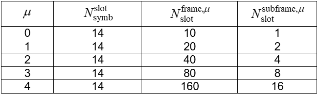
Subcarrier spacing, CP length, and the number of slots per subframe are controlled by same parameter. \(\mu (0,1,2,3,4)\)
Subcarrier spacing: \(2^\mu\cdot 15kHz\)
CP duration: \(2^{-\mu}\cdot 4.7{\mu}s\)
Each per subframe Number of time slots: \(2^\mu \)
Each slot contains 14 OFDM symbols.
one resource block includes 12 consecutive subcarriers. (A resource block (RB) consists of 12 consecutive subcarriers in the frequency domain.)
SSB

The combination of SS and PBCH is referred to as SSB in NR.
NR SS consists of primary SS (PSS) and secondary SS (SSS).
By detecting SS, a UE can
PHYSICAL Obtain The Cell Identity,
Achieve both in Downlink Synchronization Time and Frequency Domain,
The Acquire and Timing for the PBCH. Carries the PBCH Very The Basic System Information.
The starting point of the physical layer is the transport block (TB: Transport Block) transmitted from the MAC layer, and the end point is to generate the baseband OFDM signal. The up-converting or down-converting then converts the baseband OFDM signal into a radio frequency signal and transmits it through the antenna.
the TB (transport block) is the basic unit of data exchanged between the MAC layer and a physical layer for physical layer processing. The physical layer adds CRC check information to each TB.
. 5G New Radio: The Essentials Unveiling of the Next Generation The Wireless Access Technology
frame structure
SFN
SFN System Frame Number System Frame Number
Used in LTE The 10 bit carries the data, is carried in the MIB, and is transmitted in the PBCH. The SFN bit length is 10 bits, which means that the value is from 0-1023 cycles. In the MIB broadcast of the PBCH, only the first 8 bits are broadcast, and the remaining two bits are determined according to the position of the frame in the PBCH 40 ms period window, the first 10 ms frame is 00, the second frame is 01, and the third frame is 10, Four frames are 11. The PBCH 40ms window phone can be determined by blind detection.
LTE physical transmission resources (1) – frame structure and OFDM symbols
3.TDD Frame structure
The frame structure mode of the LTE-TDD protocol is generally referred to as Frame structure type 2, and is referred to herein as a TDD frame structure for the sake of clarity.
In TDD, the length of each radio frame is Tf=10ms, which consists of two “ fields ”, each “half frame” has a length equal to 5ms, consisting of 5 consecutive children. Frame composition, each sub-frame length is equal to 1ms.
When the same subframe is in different uplink-downlink configurations, data in different directions may be sent. The following figure shows the direction in which all subframes send data under various uplink and downlink subframe configurations. D indicates that the subframe can only send downlink data, U indicates that the subframe can only send uplink data, and S indicates a special subframe, which is generally used for downlink data transmission.

downlink – uplink handover period (Downlink-Uplink Switch-to-Point periodicity)
downlink – uplink handover within a 10ms period and the number of related special subframe , calculated with reference to the FIG. .